- 您现在的位置:买卖IC网 > Sheet目录222 > DS1923-F5# (Maxim Integrated)IBUTTON TEMP/HUMIDITY LOGGER F5
DS1923
iButton Hygrochron Temperature/Humidity
Logger with 8KB Data-Log Memory
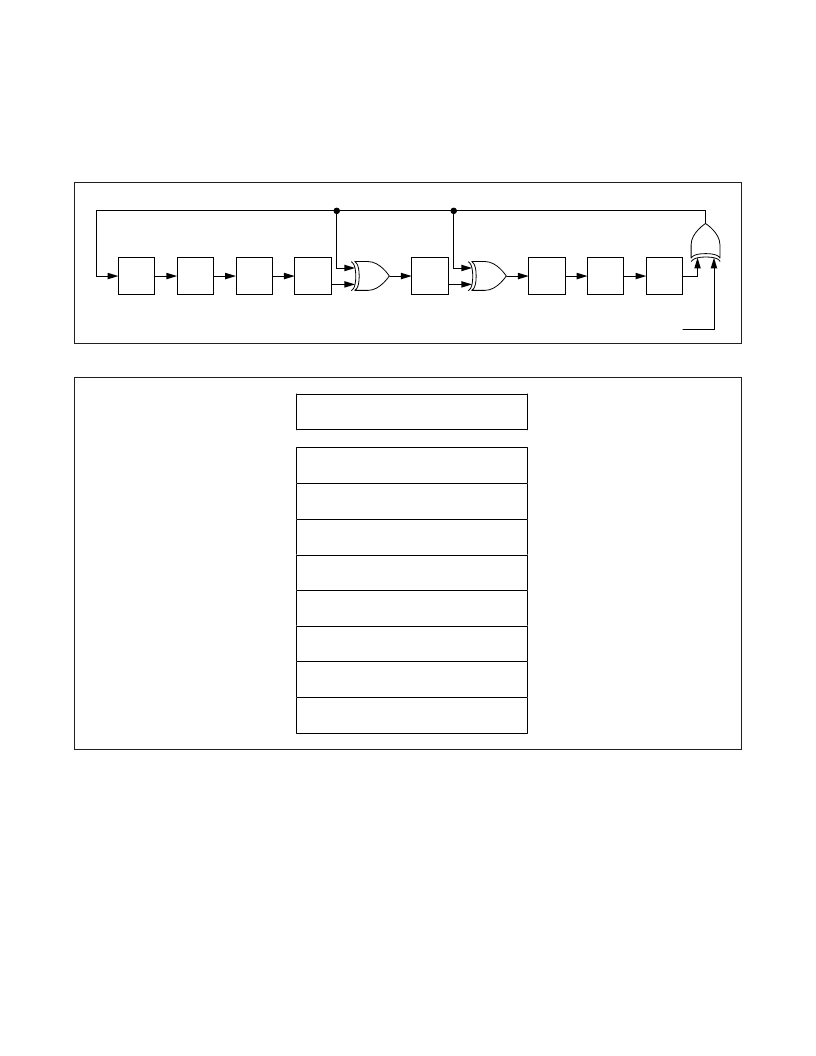
POLYNOMIAL = X 8 + X 5 + X 4 + 1
1ST
STAGE
2ND
STAGE
3RD
STAGE
4TH
STAGE
5TH
STAGE
6TH
STAGE
7TH
STAGE
8TH
STAGE
X 0
X 1
X 2
X 3
X 4
X 5
X 6
X 7
X 8
INPUT DATA
Figure 4. 1-Wire CRC Generator
32-BYTE INTERMEDIATE STORAGE
SCRATCHPAD
ADDRESS
Figure 5. Memory Map
0000h TO 001Fh
0020h TO 01FFh
0200h TO 021Fh
0220h TO 023Fh
0240h TO 025Fh
0260h TO 027Fh
0280h TO 0FFFh
1000h TO 2FFFh
32-BYTE GENERAL-PURPOSE SRAM
(R/W)
GENERAL-PURPOSE SRAM (R/W)
32-BYTE REGISTER PAGE 1
32-BYTE REGISTER PAGE 2
CALIBRATION MEMORY PAGE 1 (R/W)
CALIBRATION MEMORY PAGE 2 (R/W)
(RESERVED FOR FUTURE EXTENSIONS)
DATA-LOG MEMORY (READ ONLY)
PAGE 0
PAGES 1 TO 15
PAGE 16
PAGE 17
PAGE 18
PAGE 19
PAGES 20 TO 127
PAGES 128 TO 383
Memory
Figure 5 shows the DS1923 memory map. Pages 0 to
15 contain 512 bytes of general-purpose SRAM. The
various registers to set up and control the device fill
pages 16 and 17, called register pages 1 and 2 (see
Figure 6 for details). Pages 18 and 19 can be used as
storage space for calibration data. The data-log log-
ging memory starts at address 1000h (page 128) and
extends over 256 pages. The memory pages 20 to
127 are reserved for future extensions. The scratch-
pad is an additional page that acts as a buffer when
14
writing to the SRAM memory or the register pages.
The calibration memory holds data from the device
calibration that can be used to further improve the
accuracy of temperature and humidity readings. See
the Software Correction Algorithm sections for details.
The last byte of the calibration memory page stores an
8-bit CRC of the preceding 31 bytes. Page 19 is an
exact copy of the data in page 18. While the user can
overwrite the calibration memory, this is not recom-
mended. See the Security by Password section for
ways to protect the memory. The access type for the
Maxim Integrated
发布紧急采购,3分钟左右您将得到回复。
相关PDF资料
DS1961S-F3#
IBUTTON EEPROM 1KBit F3
DS1963S-F5+
IBUTTON MONETARY SHA-1
DS1971-F3+
IBUTTON EEPROM 256KBIT F3
DS1972-F3+
IBUTTON EEPROM 1KBit F3
DS1973-F3+
IBUTTON EEPROM 4KBit F3
DS1977-F5#
IBUTTON EEPROM 32KBit F5
DS1982-F5+
IBUTTON 1KBit ADD-ONLY F5
DS1985-F3+
IBUTTON 16KBit ADD-ONLY F3
相关代理商/技术参数
DS1923-F5#W
功能描述:iButton Hygrochron Temp/Hum Logger w/8KB DataLog RoHS:否 存储类型:SRAM 存储容量:512 B 组织: 工作电源电压:3 V to 5.25 V 接口类型:1-Wire 最大工作温度:+ 85 C 尺寸:17.35 mm x 5.89 mm 封装 / 箱体:F5 MicroCan 制造商:Maxim Integrated
DS1923-F5+
功能描述:iButton
RoHS:否 存储类型:SRAM 存储容量:512 B 组织: 工作电源电压:3 V to 5.25 V 接口类型:1-Wire 最大工作温度:+ 85 C 尺寸:17.35 mm x 5.89 mm 封装 / 箱体:F5 MicroCan 制造商:Maxim Integrated
DS19310
制造商:SANYO 制造商全称:Sanyo Semicon Device 功能描述:Color TV Owners Manual Manuel dinstructions du teleouleur Color TV Manual Del Propietario
DS193-K
制造商:Miyama Electric 功能描述:
DS193-R
制造商:Miyama Electric 功能描述:
DS193-U
制造商:Miyama Electric 功能描述:
DS193-W
制造商:Miyama Electric 功能描述:
DS193-Y
制造商:Miyama Electric 功能描述:
